Breadboard prototypes are handy. You can assemble them quickly, check if your concept works and your work is done - the tool you wanted to build can be used immediately (
see my Teensy 3.1 programmer design here). However, after a while, those flimsy cables and fragile design make you want to build something more permanent. I don't mean anything like a printed, fancy board, but just a simple, soldered solution on a stripboard. As I have one of those stripboards somewhere in my "electronics" drawer (thankfully, it's still only one drawer), I decided that it's the highest time to try to make my ATtiny85 programmer more robust and move from plastic to copper.
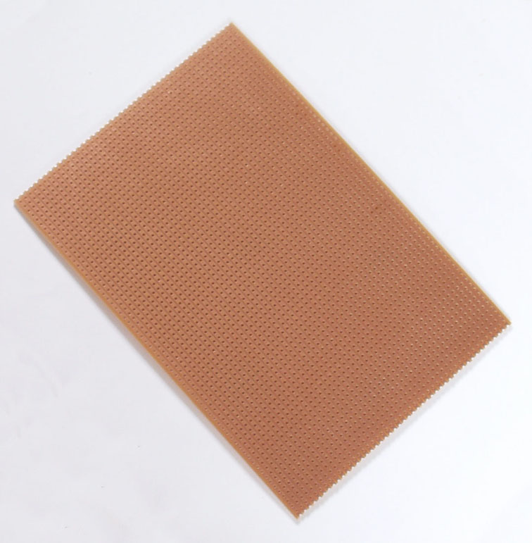
"
Stripboard" by Alexander Jones -
Own work. Licensed under Public Domain via
Wikimedia Commons.
Before I start soldering, let me gather all requirements in one place so the design is as polished as possible.
- Ideally, only one side of Teensy's pins should be used - right now, most of the programmer's pins are located on just one side of the Teensy board. There are two pins on the other side, though:
While I don't think I can relocate the 3.3V pin, PIN 13 should be easy to replace by one from the the other side of the Teensy board. This should keep the design compact and understandable but will require some changes to the Arduino ISP code.
- Microcontroller socket should be a part of the programmer board - in case the device doesn't have the programmer interface (programming is done by removing the chip), it should be possible to connect programmed chips directly on top of the programmer board.
- The board should have the ATtiny85 programming interface - 6 pins will be enough.
- The board should be as compact as possible - that goes without saying.
I think that's a complete list of my requirements. Now, let me prepare all required components. Please expect an update soon!


No comments:
Post a Comment